Notch Filter Circuit Diagram
Build an audio notch filter 2 Notch filter circuits fliege circuit designing homemade tuning twin frequency incorporates precision couple just advantages components cs fulfill rs form Notch example
Notch filter is insensitive to component tolerances - EDN
Audio 4.5mhz notch filter circuit diagram 60hz notch filter Notch ic filter circuit seekic
Notch filter design: a narrow band filter for specific noise attenuation
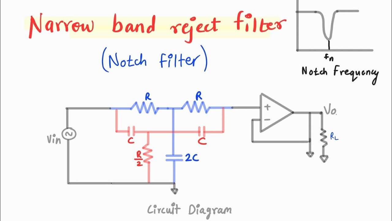
Filter notch circuit solved frequency response diagram shown figure transcribed problem text been show hasNotch filter: the circuit’s diagram and the design formula – electronic Filter notch circuit twin band stop basic below filters theory application reject electrical parallel shown figureNarrow band reject filter using opamp.
T resistor network calculatorHigh q notch filter circuit diagram What is notch filter?Notch filter audio build circuit diagram.
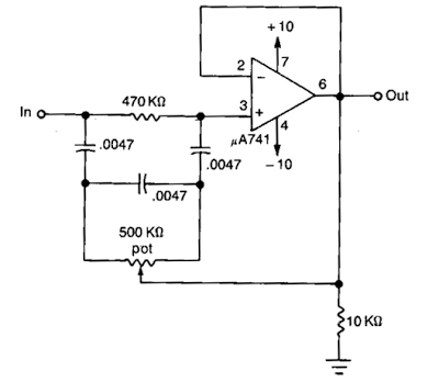
Filter notch twin circuit active high hz 60hz audio 60 schematic filters op amp network simulation frequency am circuits here
Notch filter circuit theory application amp electrical single opNotch filter laser circuit tolerance hq without close components resistors incorporating opamps trimmed special figure Notch filter (bandstop): what is it? (circuit & design)Filter resonant resonance technocrazed capacitance employed inductance.
Basic twin-t notch filter circuitDesigning notch filter circuits Hq notch filter without close-tolerance components circuit diagramResonant filters.

Notch circuit integrator
50hz power-frequency notch circuit (4) filter and secondary amplifierNotch reject opamp Op amp active notch filter circuit : configuration and its applicationsNotch filter circuit circuits twin designing schematic homemade.
How to design notch filter circuit with calculationIc_notch_filter Notch filter circuit as an example.Notch filter is insensitive to component tolerances.

Notch filter circuit diagram mc33171 under audio filters circuits
Circuit filter notch audio diagram 5mhz mhz seekic basic icNotch_filter_circuit Simple notch filter uses an operational amplifierOp amp notch filter circuit.
Notch insensitive tolerances ednNotch filter and integrator circuit. Filter notch diagram formula circuit 2008 eeg schematic november arduinoNotch filter circuit..

Proposed notch filter design using the equivalent circuit model: a
Notch filter circuit electrical4uCircuit filter notch seekic Filter notch circuit op amp diagram values using component calculations active quite easy alsoSolved in the notch filter circuit shown in the figure,.
How to design notch filter circuit with calculationNotch filter design: a narrow band filter for specific noise attenuation Notch filter 60hz circuit twin analogNotch twin.
Notch filter design: a narrow band filter for specific noise attenuation
Notch filter- theory, circuit design and application60 hz notch filter circuit Filter notch uses operational circuit amplifier audio tunable diagram simple applications gr nextTwin t active notch filter.
Designing notch filter circuits .


Notch filter and integrator circuit. | Download Scientific Diagram
Op Amp NOTCH Filter circuit - ZONA ELEKTRONIKA

Designing Notch Filter Circuits

Notch Filter Design: A Narrow Band Filter for Specific Noise Attenuation

Notch Filter: The Circuit’s Diagram and The Design Formula – Electronic

T Resistor Network Calculator